How to Read and Use McNICHOLS® Bar Grating Load Tables
McNICHOLS® Bar Grating load tables help engineers, architects, contractors, and facility managers select the correct Bar Grating based on load capacity, clear span, and deflection limits. These tables support safe, reliable performance for pedestrian, industrial, and heavy-duty applications.
This resource explains how Bar Grating load tables work, how to read them correctly, and how to apply them to real-world project requirements.
What Are Bar Grating Load Tables?
Bar Grating load tables show how much weight a specific Bar Grating configuration can safely support over a defined clear span, which is the distance between supports. Each load table factors in:
Bar Grating construction type
Bearing bar size and spacing
Material type
Load type and magnitude
Allowable deflection
Together, these values help ensure safety, durability, and consistent performance across a wide range of applications.
Step 1: Identify the Bar Grating Type
McNICHOLS® Bar Grating load tables are organized by Grating series type and name.
Example: 19-W-4 Welded Bar Grating
19 = Bearing bar spacing, 19/16 inch on center
W = Welded construction
4 = Crossbar spacing, 4 inches on center
verify the material type
Material selection directly impacts load capacity and deflection performance. Always confirm the material before referencing a load table:
Carbon Steel
Galvanized Steel
Aluminum
Stainless Steel
Each material has different strength characteristics and corresponding load values.
Consider the Surface Type
Surface type can affect the effective load-carrying capacity of Bar Grating and should be considered during selection.
Serrated bearing bars reduce the effective bearing bar height compared to smooth surface Grating. As a result, serrated Bar Grating may carry the same load as smooth Grating with a shallower bearing bar depth.
For example, a GW-150 serrated Bar Grating may have a similar load capacity to a GW-125 smooth Bar Grating due to the serrations reducing the effective bearing bar height to approximately 1-1/4 inches.
When specifying serrated Bar Grating, always verify whether adjusted load values apply to ensure the Grating meets project requirements.
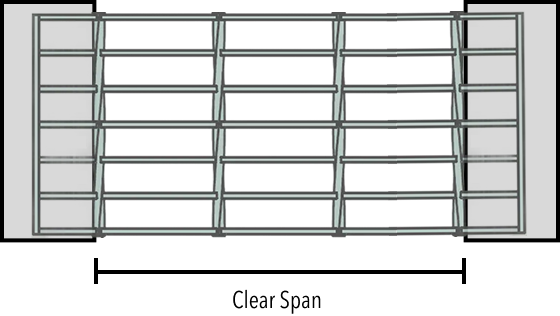
Step 2: Determine the Clear Span
Clear span is the unsupported distance between the structural supports beneath the Bar Grating.
Common Clear Spans
24 inches
36 inches
48 inches
60 inches
It's important to note, bearing bars must span parallel to the supports to achieve the load capacity shown in the table. Improper orientation can significantly reduce performance.
Step 3: Understand Bar Grating Load Types
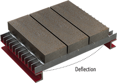
Uniform Load (U)
Uniform Load
To clarify, uniform loads are evenly distributed across the Grating surface and are measured in pounds per square foot, or psf.
Typical uniform load applications include:
Walkways
Platforms
Mezzanines
Catwalks
Standard pedestrian design load: 100 psf
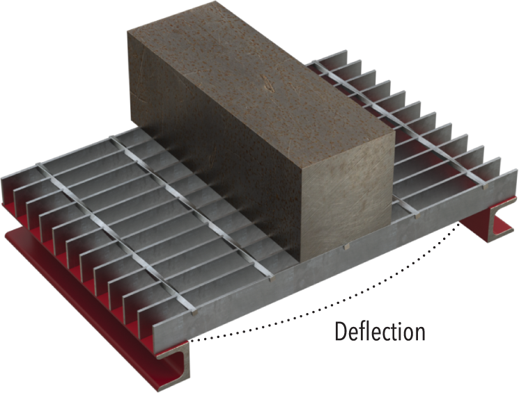
Concentrated Load (C)
Concentrated Load
In contrast, concentrated loads are applied over a smaller area and are measured in pounds per foot of width.
Common concentrated load applications include:
Forklifts
Maintenance carts
Service vehicles
When using concentrated load tables, always design for the maximum wheel or point load expected during service.
Step 4: Review Deflection Limits
Deflection measures how much the Bar Grating bends under load.
Typical Pedestrian Deflection Limits
L/400, or
1/4 inch maximum deflection
Even if a Grating meets load capacity requirements, excessive deflection may feel unsafe or uncomfortable for foot traffic.
Example: Pedestrian Walkway Bar Grating Selection
Project Requirements
Clear span: 48 inches
Design load: 100 psf
If the load table confirms the selected Bar Grating supports 100 psf at a 48-inch span with a deflection of 1/4 inch or less, the Grating is suitable for the application.
If not, consider:
Reducing the clear span
Selecting a deeper bearing bar
Choosing a heavier-duty Bar Grating configuration
Heavy-Duty and Vehicle Loading Applications
Heavy-duty Bar Grating load tables should be used when loads exceed standard pedestrian conditions or are highly concentrated.
Typical applications include:
Forklift traffic
Maintenance and service vehicles
Truck access areas
Industrial ramps
Vehicle loading applications should always be reviewed by a qualified engineer to confirm suitability.
Bar Grating Support and Bearing Requirements
Proper support conditions are critical to achieving the load capacities shown in Bar Grating load tables.
Industry guidelines recommend minimum bearing surface requirements based on Grating depth:
A 1-inch minimum bearing surface for Bar Grating depths up to 2-1/4 inches
A 2-inch minimum bearing surface for Bar Grating depths of 2-1/2 inches and greater
Adequate metal support at each end of the span is required to ensure structural performance and long-term durability.
Important Bar Grating Design Considerations
Load tables assume proper installation and full bearing support
Serrated bearing bars may require adjusted load capacities
Load tables provide general guidance and do not replace project-specific engineering analysis
Critical structural applications should be reviewed by a licensed engineer
Access Official McNICHOLS® Bar Grating Load Tables
For official load ratings and detailed performance data, download the McNICHOLS® Bar Grating Load Table PDFs from the Product Resources section.
McNICHOLS is the leading supplier of Specialty Metal and Gratings, in the U.S. and has 19 locations nationwide. We are ready and Inspired to Serve® you at 855.318.8791, [email protected], or via Live Chat on mcnichols.com.